Contours ↩
Description
Contours are visual descriptions of glyph shapes using bezier curves.
Bezier curves were introduced into type design in the 1980s as two competing flavors, PostScript (Adobe) and TrueType (Microsoft/Apple). The PostScript format used cubic bezier curves, while the TrueType used quadratic ones. The formats evolved and were merged into the OpenType format, but the distiction remains between OpenType-CFF (cubic) and OpenType-TTF (quadratic) fonts.
The Ikarus format which existed before that was based on circle segments.
Contours can be made of line and curve segments.
- Line segments
- are made of two on-curve points
- Curve segments
- are made of two on-curve points and off-curve points
Contours can be open or closed. Open contours are allowed in UFO, but not in OpenType.
Cubic and quadratic beziers
RoboFont uses cubic bezier curves by default. This is the type of contours which is most familiar to designers, since it’s used by vector design applications. Cubic beziers are part of Adobe’s PostScript page description language, and are used by OpenType-CFF fonts.
Since version 4.0, RoboFont offers full support for quadratic bezier curves. This allows for a finer control over outlines meant to be exported as TrueType fonts.

- UFO3 specification allows the existence of both quadratics and beziers segments in the same contour. RoboFont abides to the specification, be aware!
Point smoothness
Bezier points can be smooth or unsmooth.
- smooth point
- segments are continuous
- unsmooth point
- segments are at an angle
Point smoothness can be toggled on / off by double clicking the point.
Smooth points retain continuity between segments when its handles are moved.
The angle of handle is locked to the angle of the opposing line segment of or to the angle of the handle of the oppposing curve segment.
Point representations
Points are represented by different icons depending on their smoothness and the type of segments they connect:
| Icon | Description |
|---|---|
|
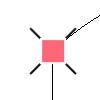
Square Unsmooth connection between line and curve segments, two line segments or two curve segments where the handles can move independently |
|
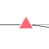
Triangle Smooth connection between line segment and curve segment |
|
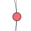
Circle Smooth connection between two curve segments, handles locked to the same angle |
|
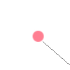
Control point only connected to anchor Cubic bezier control points. Cubic beziers only allow for two control points, each one connected to an anchor |

|
Connected control points Quadratic bezier control point. Quadratic beziers allow for an infinite amount of control points. By default they have a different color from cubic off curves |
|
Circle or square with cross underneath On-curve point matching with off-curve point |
|
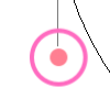
Circle around on-curve or off-curve point Signals the first point in the contour, either on-curve or off-curve |
|
|
Arrow Placed on the first on-curve point of the contour (there might be off-curve points preceding it), it indicates the direction of the contour |
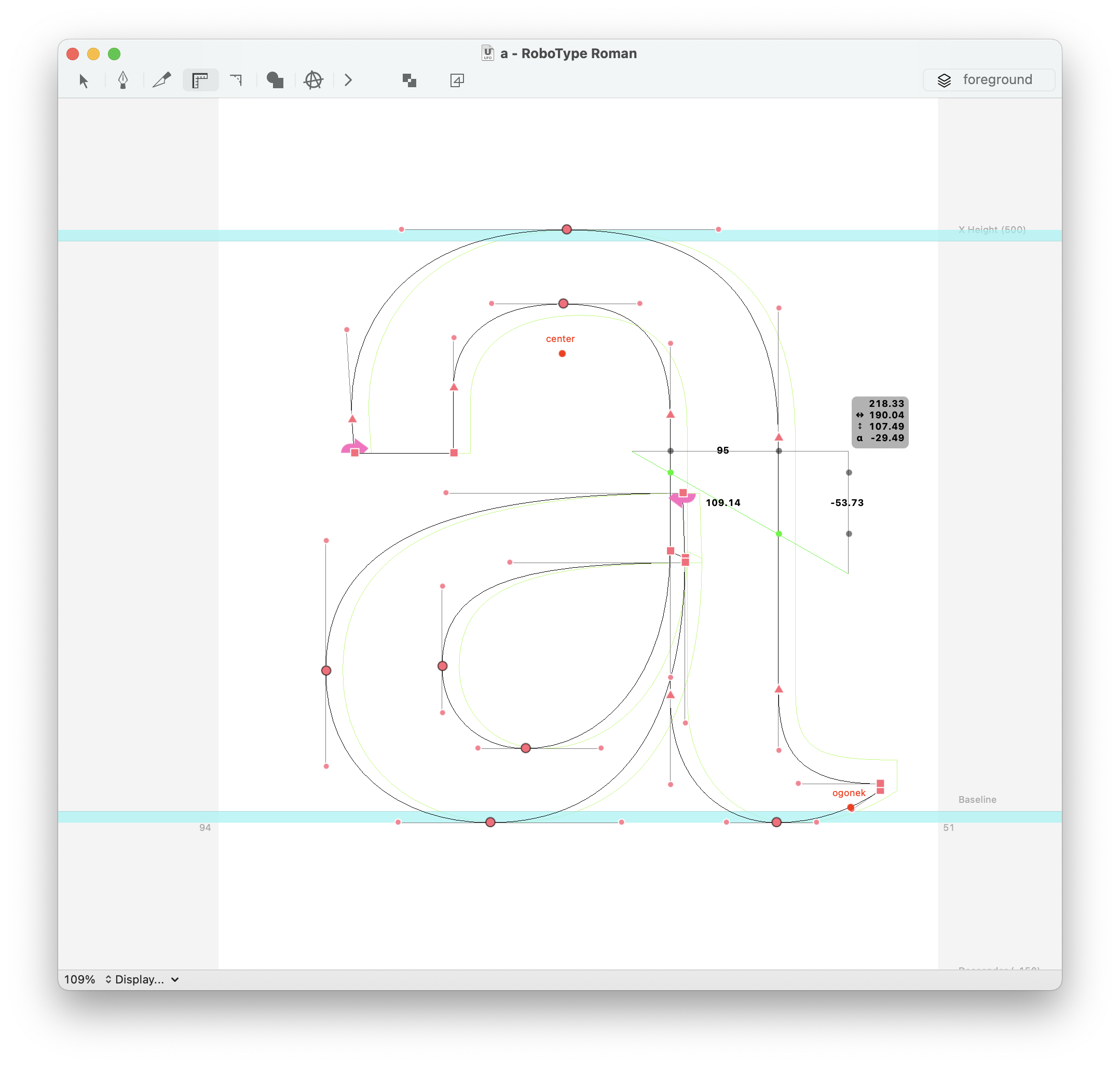
Creating and editing contours
Contours are usually created using the Bezier Tool and edited using the Editing Tool. It is also possible to draw inside a glyph with code – see this example.
Contours Inspector
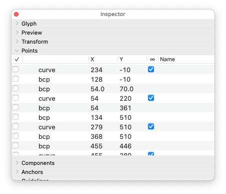
Contour and point properties can be edited in the Points section of the Inspector.
First Contour Point
According to the UFO specification, an open contour must start with a move type point:
<?xml version='1.0' encoding='UTF-8'?>
<glyph name="contours" format="2">
  <advance width="500"/>
  <outline>
    <contour>
      <point x="144" y="314" type="move"/>
      <point x="204" y="159" type="line"/>
      <point x="251" y="117"/>
      <point x="308" y="100"/>
      <point x="377" y="106" type="curve"/>
    </contour>
  </outline>
</glyph>
while a closed contour can start with either curve, line or qCurve point
<?xml version='1.0' encoding='UTF-8'?>
<glyph name="contours" format="2">
  <advance width="500"/>
  <outline>
    <contour>
      <point x="120" y="167" type="line"/>
      <point x="64" y="314" type="line"/>
      <point x="96" y="150" type="line"/>
    </contour>
    <contour>
      <point x="164" y="314" type="curve"/>
      <point x="224" y="159" type="line"/>
      <point x="178" y="203"/>
      <point x="158" y="254"/>
    </contour>
    <contour>
      <point x="324" y="159" type="qcurve"/>
      <point x="264" y="314" type="line"/>
      <point x="260" y="269"/>
      <point x="290" y="192"/>
    </contour>
  </outline>
</glyph>
If you want to inspect closely the content of a glif file inside a UFO, you can use the glifViewer extension by Frederik Berlaen. Using the same extension, you can paste these examples and observe the outlines directly in RoboFont
As you can see from the previous examples, off-curve points do not have a type attribute, as they can be inferred based on their relative position to the on-curve points. So, it is possible to move an off-curve point at the top of the list without breaking the UFO specification.
<?xml version='1.0' encoding='UTF-8'?>
<glyph name="contours" format="2">
  <advance width="500"/>
  <outline>
    <contour>
      <point x="260" y="269"/>
      <point x="290" y="192"/>
      <point x="324" y="159" type="qcurve"/>
      <point x="264" y="314" type="line"/>
    </contour>
  </outline>
</glyph>
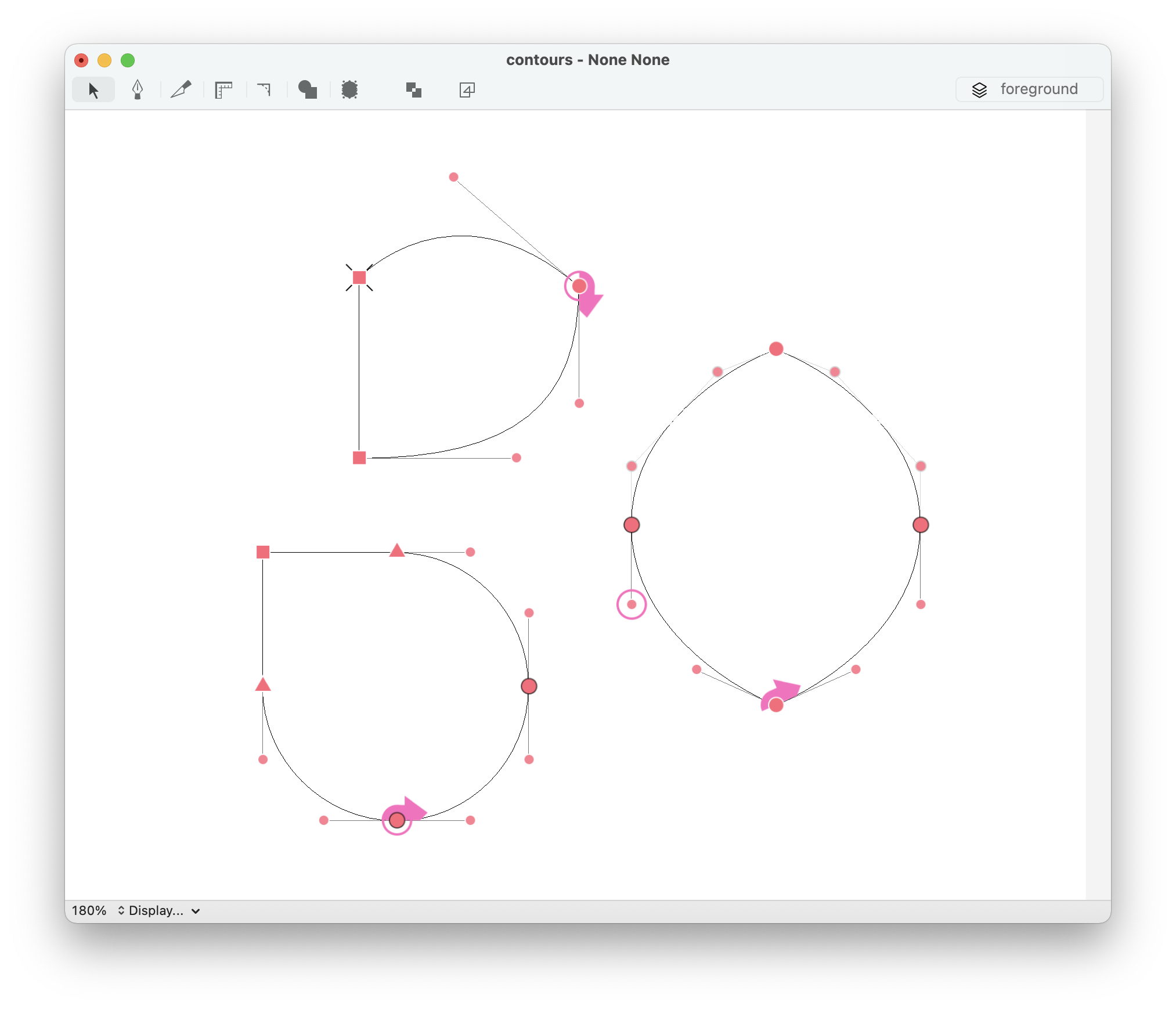
This is not an issue while interpolating outlines with RoboFont or Skateboard, because their underlying API – fontMath – automatically picks the first on-curve point as the first contour point. Differently, tools like fontMake require strict compatibility between outlines, so if contour FOO starts with an off-curve point, contour BAR should do the same.
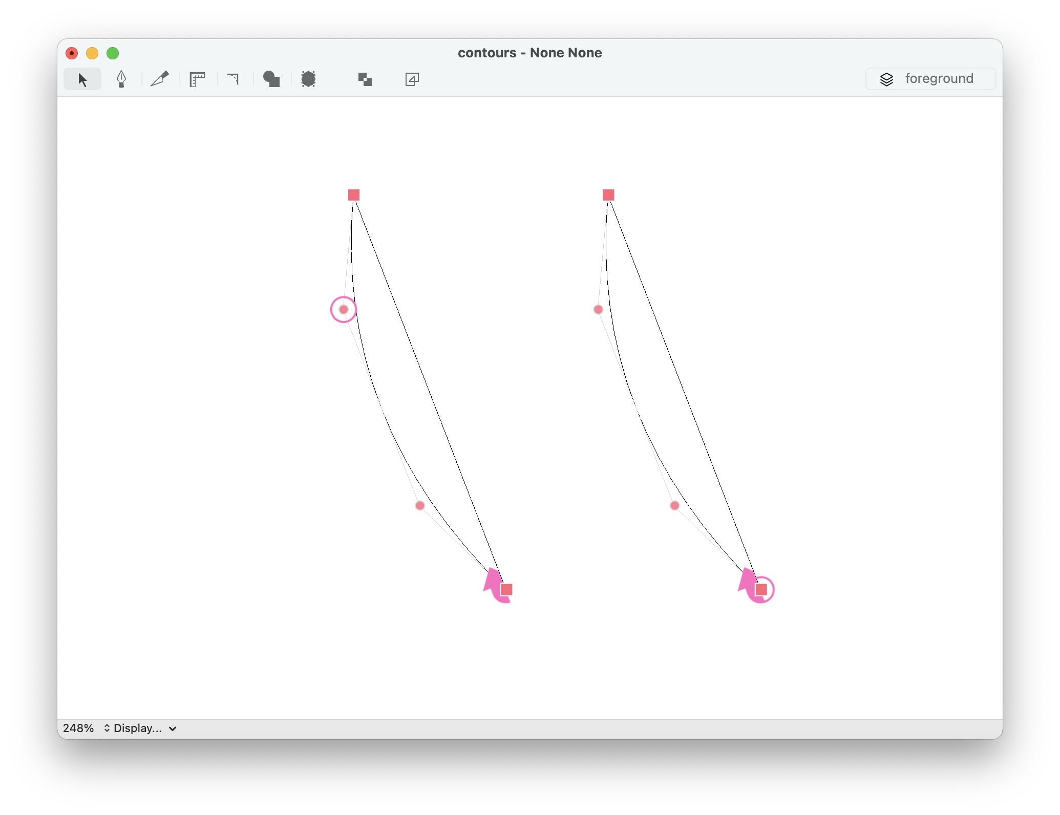
To provide finer control over outlines compatibility, RoboFont visualizes the first point of the contour on an off-curve point if necessary, which will detach the “first contour point” icon from the arrow that indicates the contour direction.
Contextual menu
The contextual menu can be opened with a right-click using the Editing Tool. A different set of options is displayed depending on the context:
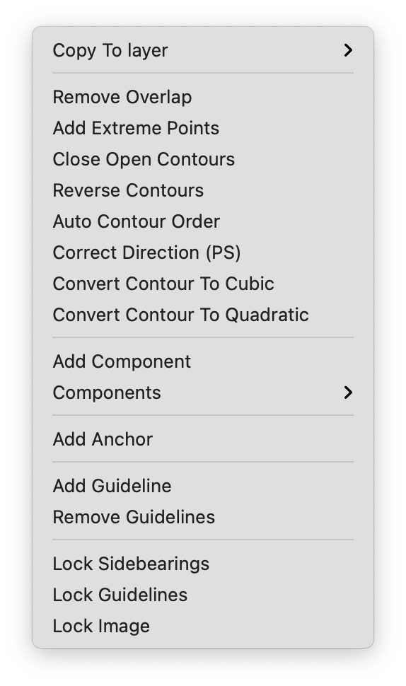
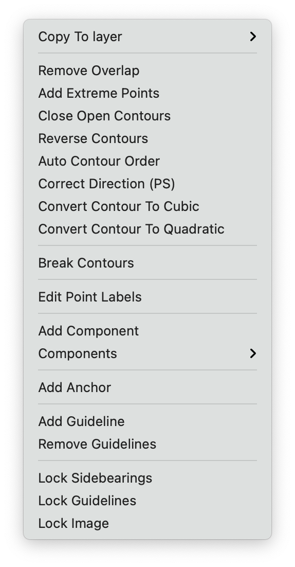
Contour / Multiple points selection actions
| action | description |
|---|---|
| Remove Overlap | Remove overlaps in the selected contours |
| Add Extreme Points | Add extreme points to the selected contours |
| Close Open Contours | Connects two start or end points included in the selection, giving priority to start and end points of the same open contour. The selection might include non-end points, they will be ignored |
| Reverse Contours | Reverse selected contours |
| Convert Contour to Cubic | Convert selected contour or segments to cubic |
| Convert Contour to Quadratic | Convert selected contour or segments to quadratic |
| Break Contours | If an entier contour is selected, the contour is deleted. Otherwise only the selected segments are deleted |
| Edit Labels | Edits labels to the selected points |
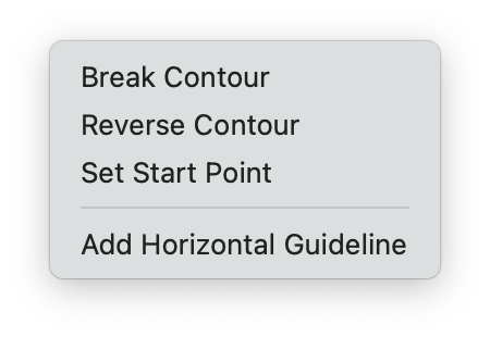
Single point actions
| action | description |
|---|---|
| Break Contour | Breaks contour at the selected point |
| Reverse Contour | Reverse contour |
| Set Start Point | Set the selected point as starting point |
| Add Horizontal Guideline | Adds a horizontal guidelines lying on the selected point |
- UFO3 Specification > glyf > Point
- FontParts API > RContour / RPoint / RBPoint / RSegment